By Anna Tiburzi
Alright, I know what I said last time about transitioning into Lumion and I promise we’re getting there, but after seeing the island in person and looking through some more photos and references, there was still more to do.
I’ve spent the past two weeks getting the models where I really want them – materials, seawalls, building treatments, and missing planar geometry being the biggest goals I had.
Materials
Material applications have been in the works for a couple weeks now, but we’re finally at the point where not only are the ground plane materials applied, but those needed for buildings, the fort, or other geometry have been applied as well.
The existing buildings had all originally been treated with the same “wood” texture to identify them. After working with my counterparts at the OCLP in Boston and doing some more deep diving into the historical references at hand, I was able to find the general materials and characteristics for many of the buildings in the plans and apply those textures to give the models just that much more variability and detail. Same goes for the ground plane textures and any missing geometry that had to be modeled.
I kept as many materials as I could uniform between all six models to give the models a level of cohesion when compared side by side.

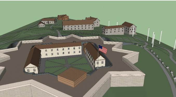
Figure 1: A Top Down View of the 2019 Model
The Seawall
The seawall posed a frustrating challenge. There was no easy way to put it in and the contour information for each model and CAD file didn’t give me much of an idea except for where they generally might have went, indicated by overlapping contours lines at the edge of the island’s perimeter. The first seawall (implemented 1811-1842) not only expanded over time to wrap further around the island, but also changed to take into consideration the new shorelines that developed over the years as areas were filled in and land added.

Figure 2: Changes in the Island’s Shoreline Throughout History
Taking what information I could from historical photos and plans, I put in where I could best estimate the seawall’s location for each model. My initial idea was to offset the exterior boundary of the island 40” (as that’s the current day’s width of the seawall) and pull down the wall to create a flat edge, however, it became clear pretty quickly that this wasn’t going to be a feasible strategy. The exterior of the island wasn’t coplanar and therefore the perimeter couldn’t easily be offset using the Offset Tool. I had no easy way of laying down a second line to mark the footprint of the wall.
I had used a similar technique to create the 16″ seatwalls around the island, laying down the outlines for the walls and pulling up from the mesh 14” before using the Follow Me tool to create a 2” cap on top to hide any irregularities resulting from manipulating the mesh in this way which might show in the final model. While good for the seatwalls, it didn’t seem to be working efficiently for the seawall.
My second attempt was to push/pull out the topmost layer in the mesh and then pull down to create a flat wall. Unfortunately, the edges of the mesh weren’t all rectangular or on axis. So pulling them out and down created odd angles and shapes where it did work and conspicuous gaps where it didn’t. Another bust.
The third attempt was to isolate the contour line that could best represent the wall’s location. Contour lines exist on the same plane by definition, so I was able to offset them 40” to create a ring shaped like the seawall and then pull it down straight. I eliminated areas that wouldn’t have had a seawall yet for the appropriate time periods and added a tumbled brick material to identify it as the seawall. I then moved areas of the wall up or down to be flush with the adjacent terrain. This technique, while not perfect, seemed to work the best and gave the closest representation of the wall that we were looking for. I guess it’s true what they say, third times the charm.

Figure 3: View of the 2019 Seawall
Building Treatments
After assessing the overall character of the buildings in the historical photos, I applied these general characteristics to the buildings in the models. The goal was not to model each building exactly as it had been, down to window location and doorknob – that would require more time and be much more labor intensive – but to give the idea of what these buildings looked like, adding another level of realism to the models as they move forwards. They’re no longer little wooden monopoly houses – different materials and treatments have given them a variation and depth that make the model more immersive.

Figure 5: The 1880 model after building treatments had been applied.
Planar Geometry
Besides the fort entrance, fort coping stones, and the seawall, which all six of the models were lacking, each of them required some level of further development for missing stairs, walls, or other geometry. The current day model was missing the most and I spent a fair amount of time adding any elements and details that I had noted on my field visit, including the entrance walls, fort and pedestal stairs, terreplein material pattern, and building stairs, doors, and windows.

Figure 6: Different 2019 Models

Figure 7: Yes! Progress!
So where does that leave us now? Well, now I start looking at the models in Lumion, getting a feel for them, setting up vantages, applying textures, adding objects or other components, atmosphere, etc. – there’s a lot left to do. I may have to dip back into SketchUp again to make changes, but it’s pretty clear that even though modeling is mostly done, I’m going to be busy for a while.
It hasn’t exactly been an exciting two weeks, but I’m more and more satisfied with the models as they progress and I’m ready to start moving into Lumion – I mean it this time!