By Anna Tiburzi
Another couple weeks have come and gone and I’ve been working near exclusively on model development. I’m going to go into a bit of what I’ve been focused on recently and, for those of you unfamiliar with SketchUp, I’ll describe a few of the tools and methods I’ve used.
One of the biggest challenges this past week has been cleaning up the meshes which I generated a couple weeks ago. These meshes act as the terrain for each model and are created from the existing contour information and layers from the CAD files for each of the six models. These contours can be brought into SketchUp from CAD and using the “From Contours” tool in the Sandbox Toolbar, can be turned into landforms.

Figure 1: The 1952 model before and after the mesh generation
While the meshes were informative and smoothed out much of the terrain, there were several areas in each model that had inconsistencies or generated incorrectly. Walkways were bumpy when they should be smooth, edges where the seawalls are were all over the place – anywhere where planar geometry was supposed to be (walls, stairs, etc.) didn’t quite generate accurately.

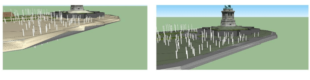
Figure 2: Errors in the mesh generation at the sea wall, before and after (1952 model)
I tried a couple different methods to smooth them out, but as tends to be the case, the hard way proved the most effective method – entering the terrain mesh groups and going in by hand to clean them up. Terrains generated in SketchUp result in a mesh “group” which you can enter and alter from inside without compromising the rest of the model. Once inside, I erased incorrect connections and generated smaller terrain meshes in certain areas to patch them back up. There’s a certain amount of satisfaction when you fix up a mesh and see it fall back into place cleanly. I also started putting in some of that missing planar geometry, though there’s still a ways to go on that front, especially with the seawall.

Figure 3: Errors in the mesh generation are often associated with intersecting planar geometry such as stairs (top) and walls along paths (bottom). Here I’ve addressed the issues and resolved the geometry.
Now that the meshes are good to go, the next task I wanted to tackle was pathways. Going back to the CAD files once again for each model, I isolated the path information that I wanted and erased any extra data that wouldn’t be helpful and saved them each as new CAD files to be imported into the models. Like meshes, CAD files come in as a group. Using the “drape” tool, these lines can be dropped onto the new terrain mesh. This will make it possible later to add colors and textures to certain areas to separate out where different materials will go.

Figure 4: An axonometric of the 1952 model showing the model base (bottom), the terrain mesh with materials added (middle), and paths layer that was draped onto the mesh (top).
Unfortunately, not all of the paths draped successfully. This happens sometimes, it just means that the paths weren’t quite connected at all their corners and intersections. That’s easy enough to clean up – either redrawing lines with “hidden geometry” turned on (which makes it possible to see all the triangular planes that make up a mesh surface) or by drawing new lines and draping those down onto the mesh to connect back up all the gaps. Once they’re all connected up, materials (colors and textures) can be added to differentiate the surfaces.

Figure 5: Sometimes the lines that make up the paths aren’t quite connected at all their intersections, causing selections to be inaccurate. By closing the gaps, areas are separated and ready for material and texture fills.
I haven’t finished putting the meshes and materials together completely for each model, but they’re all well underway. While the before and after from two weeks ago to today may not look drastically different for each model, the time put in to clean them up and apply materials will make it much easier later on for when they’re brought into another program for further rendering.

Figure 6: Before and after of the 1937 model (top) and the 1952 model (bottom).
Finally, the last little bit I’ve been working on are building treatments. The buildings in the models aren’t very detailed and with a little work here and there they could be made more convincing. To get each one perfectly accurate however, would require a fair amount of legwork and time. Another option is to create general building “treatments” which could be applied quickly, relatively speaking, to the buildings. Going back through the historical photos, I’ve found general styles and ideas that could be added. Treatment options right now are focused on roofs, window style, and chimneys. Deciding what treatments we’re going to move forward with hasn’t been finalized or discussed yet – I’ll be working on that with my mentor, Professor Aidan Ackerman (at SUNY ESF), and the folks at NPS – but I’ve been collecting and creating some options that can be picked from or mixed and matched to keep the character of the buildings during each time period.

Figure 7: Examples of buildings from the historical photos and conceptual treatments to be further developed and applied at a later date.
There’s more to be done before the models are ready for rendering, but they’re coming along. Some days and tasks prove more challenging than others, but there’s a lot to be learned from them, both about my own skills and the nuances of the programs that I’m using. For now, I’ll keep moving the models along and getting them ready for the next stage.
Stay tuned!